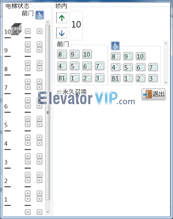
For example: Change ‘-1’ to ‘B1’
1) Keep the PP7 interface of KCD-911A board to connect MC interface of MC card by parallel ribbon data cable, and then USB interface of MC card to connect PC (or laptop) by USB cable.

Connection Schematic Diagram of Mitsubishi KCD-911A Board, PC, and MC Card
2) Keep the model of KCD-911A board works in normal mode (Not writing mode, the 7-segment display doesn’t display ‘FLS’). Adjust SW1=1, SW2=0 potentiometer of MC card.
3) Launch the software ‘MTS-II’ (MC card software) on the PC (or laptop), input the password.

Mitsubishi Elevator MTS-II Software
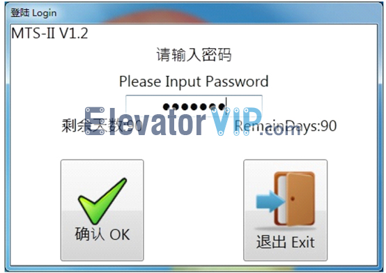
Mitsubishi Elevator MTS-II Software Login
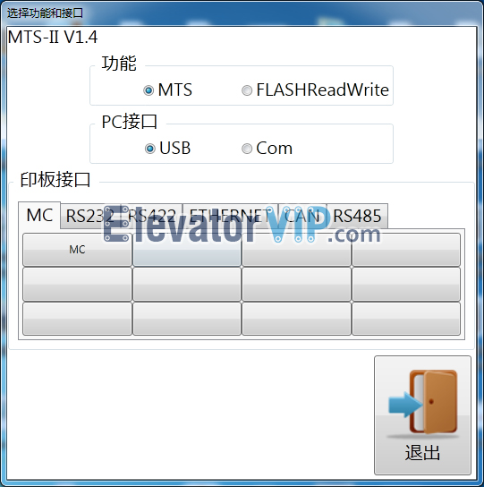
4) Select the ‘MTS’ radio button in Function block, and then select the ‘USB’ radio button in PC Interface block, also select ‘MC’ in the MC tab-page of PCB Interface block.
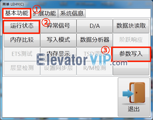
5) Click on ‘Running state’② in the Basic function tab-page①
6) Check whether where is displaying ‘-1’ in the COP, if it is, exit ‘Running state’.
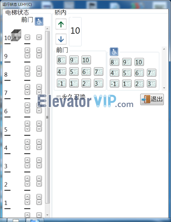
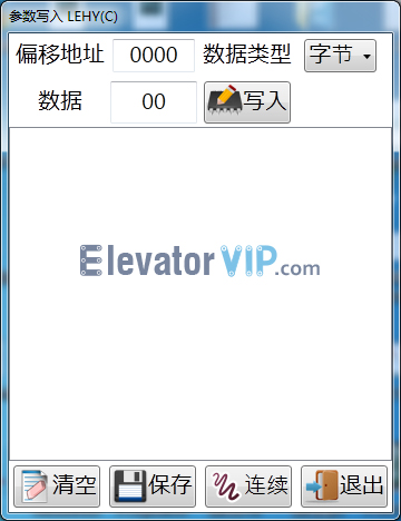
7) Click on ‘Write parameters’③ in the Basic function tab-page① to enter changing parameter mode
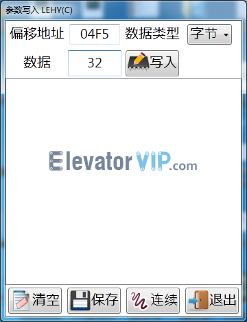
8) Input the offset address ‘04F5’ (this is the address where is ‘-1’ stored), then the value of ‘32’ (means ‘-1’) will be read auto automatically from memory.
9) Input value ‘3E’ (means ‘B1’) into the data input box, click on save button, and then exit it.
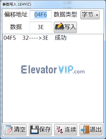
10) Check whether where is displaying ‘B1’ in the COP, if it is, successful.
